
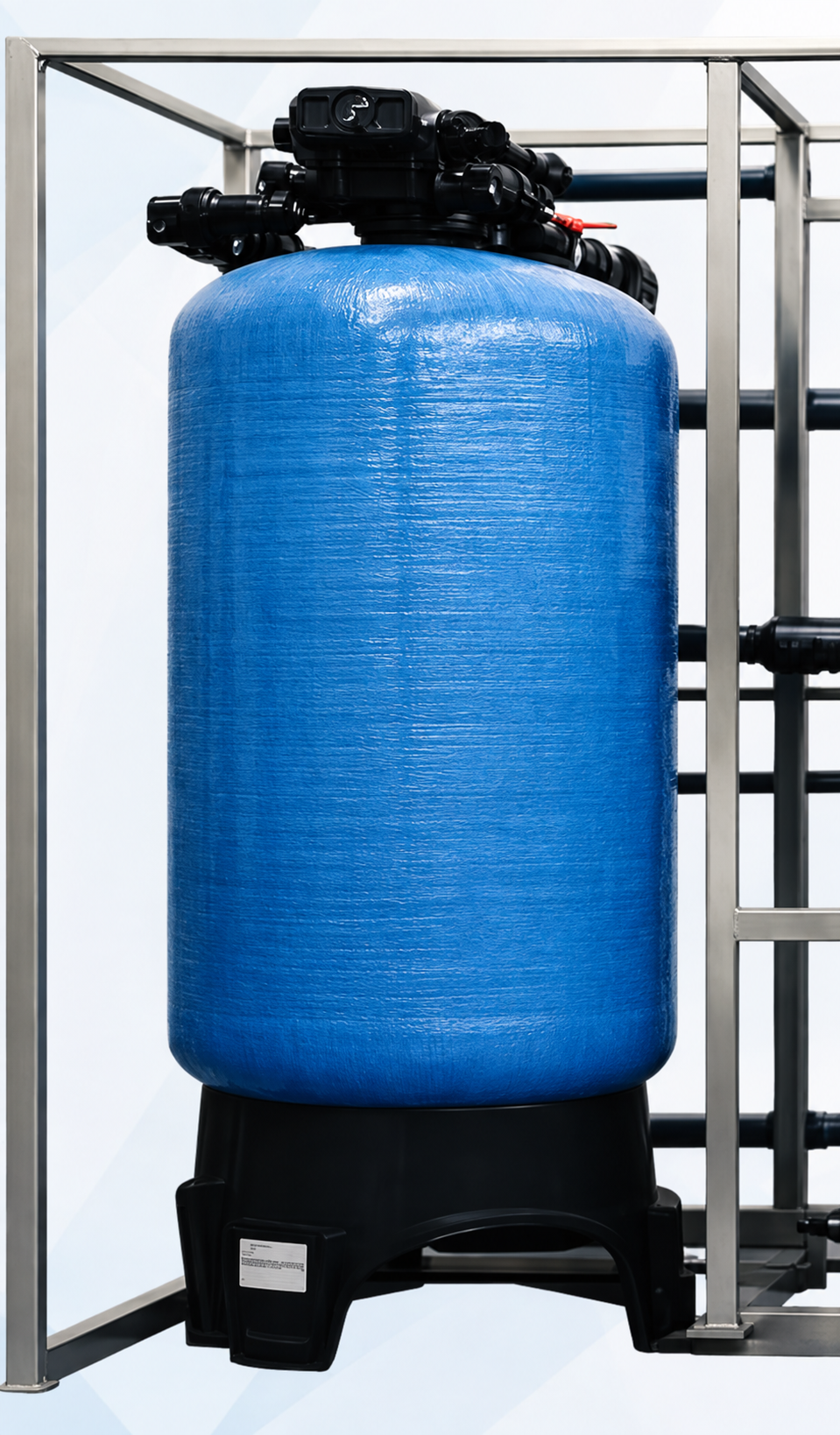
Mixed Bed Unit – 5 m³/Hr
High Purity Water Polishing System
The Mixed Bed Unit is designed for final polishing of demineralized water, using mixed cation and anion exchange resins to achieve very high purity and low conductivity. It removes both cations and anions in a single vessel pass, making it suitable for industrial and commercial applications that demand consistently high water purity.
- Capacity
- 5 m³/Hr
- Raw Water TDS
- 1000 ppm
- Hardness
- 400 ppm as CaCO₃
- pH Range
- 6.5 – 8.5
- Temperature
- 5 – 45°C
- Resin
- Mixed Bed Resin
Engineered for Consistent High-Purity Output
- Mixed Bed Unit is designed for final polishing to achieve demineralized water with very low conductivity.
- Removes both cations and anions using mixed bed resin.
- Automatic operation with simple & reliable system.
- Regeneration with HCl & NaOH solution.
- Mild Steel vessel with premium quality resin for high efficiency.
- Internal glass/FRP lining ensures corrosion resistance & long life.
- Suitable for Industrial & Commercial applications.
- Easy operation, low maintenance & longer life.
Basic Design Data
| Capacity | 5 m³/Hr (Design) |
|---|---|
| Operation Hours | 10 Hrs/Day |
| Raw Water TDS | 1000 ppm |
| Hardness (as CaCO₃) | 400 ppm |
| pH Range | 6.5 – 8.5 |
| Temperature | 5 – 45°C |
| Resin Type | Mixed Bed Resin |
| Vessel Type | MSEP (Mild Steel) |
| Vessel Internal Lining | Epoxy + FRP Lining |
| Vessel Internal | Glass / FRP |
| Regeneration Type | HCl + NaOH Solution |
| Regeneration Cycle | 10 Hrs |
| Total Connected Load | 4.5 kW (Approx.) |
| Area Required | 20 ft (L) x 12 ft (W) x 10 ft (H) |
Regeneration Details
Regeneration Type
HCl + NaOH Solution
Regeneration Tank Capacity
500 Liters (Each)
Regeneration Water Consumption per Cycle
Service Flow Rate
5 m³/Hr
Backwash Water
1.5 m³
Slow Rinse Water
1.0 m³
Fast Rinse Water
1.0 m³
Total Water Consumption
3.5 m³ / Cycle
HCl Consumption
20 – 25 L / Cycle
NaOH Consumption
20 – 25 L / Cycle
Process & Piping Flow
Full process and piping flow diagram for the Mixed Bed Unit, covering the service, dosing and backwash circuits.
Service Flow
Regeneration Circuit
Backwash Circuit
Pump Design Data
| Pump | Service | Capacity | Head | Power | Qty |
|---|---|---|---|---|---|
| Raw Water Pump | Raw Water Transfer | 5 m³/Hr | 20 m | 1.1 kW | 1 |
| Backwash Pump | Backwash Service | 5 m³/Hr | 18 m | 1.1 kW | 1 |
| Dosing Pumps | Chemical Dosing (HCl + NaOH) | 20 LPH | 10 m | (Each) | 1 |
Equipment List
| Sr. | Equipment | MOC | Qty |
|---|---|---|---|
| 01 | Mixed Bed Pressure Vessel | Mild Steel with Glass Lining | 1 No. |
| 02 | Raw Water Pump | CI / SS | 1 No. |
| 03 | Backwash Pump | CI / SS | 1 No. |
| 04 | Acid Tank (HCl) | HDPE | 1 No. |
| 05 | Caustic Tank (NaOH) | HDPE | 1 No. |
| 06 | Dosing Pumps (HCl + NaOH) | PP / PVDF | 2 Nos. |
| 07 | Interconnecting Piping | MS / GI | Lot |
| 08 | Butterfly Valves | CI / DI | 6 Nos. |
| 09 | Control Panel | Auto / Manual | 1 No. |
| 10 | Instrumentation | As per Scope | Lot |
Need a Water Treatment System for Your Facility?
Talk to our engineering team about your flow rate, water quality and treatment requirements.